Below is the Inverter & mains change over circuit,
in this circuit both Inverter supply & mains supply
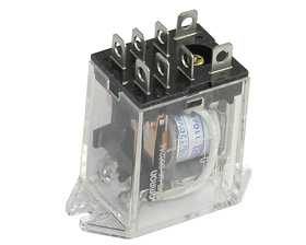
combined which is called UPS , for this purpose 8 pin DPDT relay (220 V )
were used as explain in the diagram ,
Blue wires are for Inverter ON & OFF switch,
in absence of MAINS supply Inverter will be in ON condition (pin 1
connected to 4), as can be see in diagram,
One of the wire from mains, Inverter &
output are kept common,
Pin # 8 is common for 5 & 6 pin, where main
connected to pin 6 & Inverter to pin 5.
Green wires to pins 2 & 7 are relay energizing
points, where both wires are connected to the mains,
In absence of mains Inverter will be in on
condition due to pin 1 & 4 connected, supply from
Will be available due to pins 5 & 8 connected each
other,
In the other hand if mains supply came relay will
be energize due to pins 2 & 7 , pins 6 will connect to 8,
Pin 1 will be
disconnected from 4, Inverter will be off.
You use generator
instead of Inverter but the Technic is same
Keep in mind that one wire from mains supply , invertor & output must common


No comments:
Post a Comment